Blast From the Past
Out of the blue, I got an email from Finland asking about a post I did back in 2014 about a Split Junk sail prototype. Since then I built a nicer sail, which used a different (dare I say improved) process. Life being what it is, I never documented it. That was two years ago, so this post is an attempt to dredge that improved process out of the memory fog.
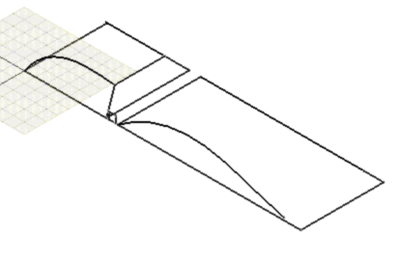
First, specify the sail parameters and feed them into my sail design program, which is a FreeCAD extension script. You can then view the sail from diffrent angles.
 I particularly like to look at the side view and visualize it as a single panel to make sure the settings for the jib and main panels mesh well together and the airflow looks right. This sail used much more aggressive camber than my first prototype: 20% jib and 7% main.
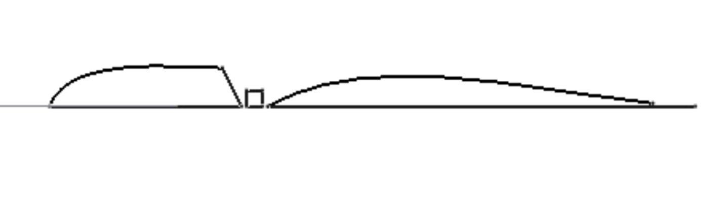
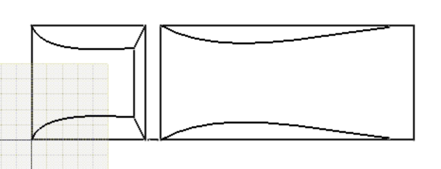
The visualizations are just to make sure everything looks right. They don’t help you actually build the sail. The program also outputs a set of coordinates you can use to make sail templates.
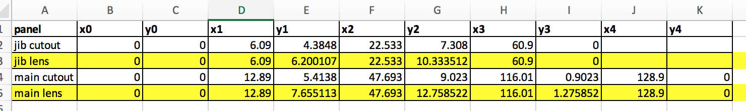
The first split junk prototype I built used both the “cutout” and “lens” coordinates to make two separate templates for each panel which were used to cutout the center and sides on flat fabric.
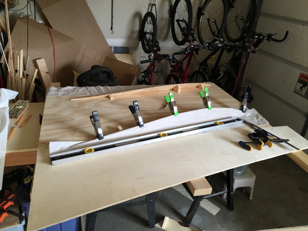
For the second sail, I made a full size plywood 3D template. This requires only using the lens coordinates (in yellow above). The previous post shows how to make the templates. Basically, you put a nail at each x,y coordinate, bend a batten around them, trace and cut.
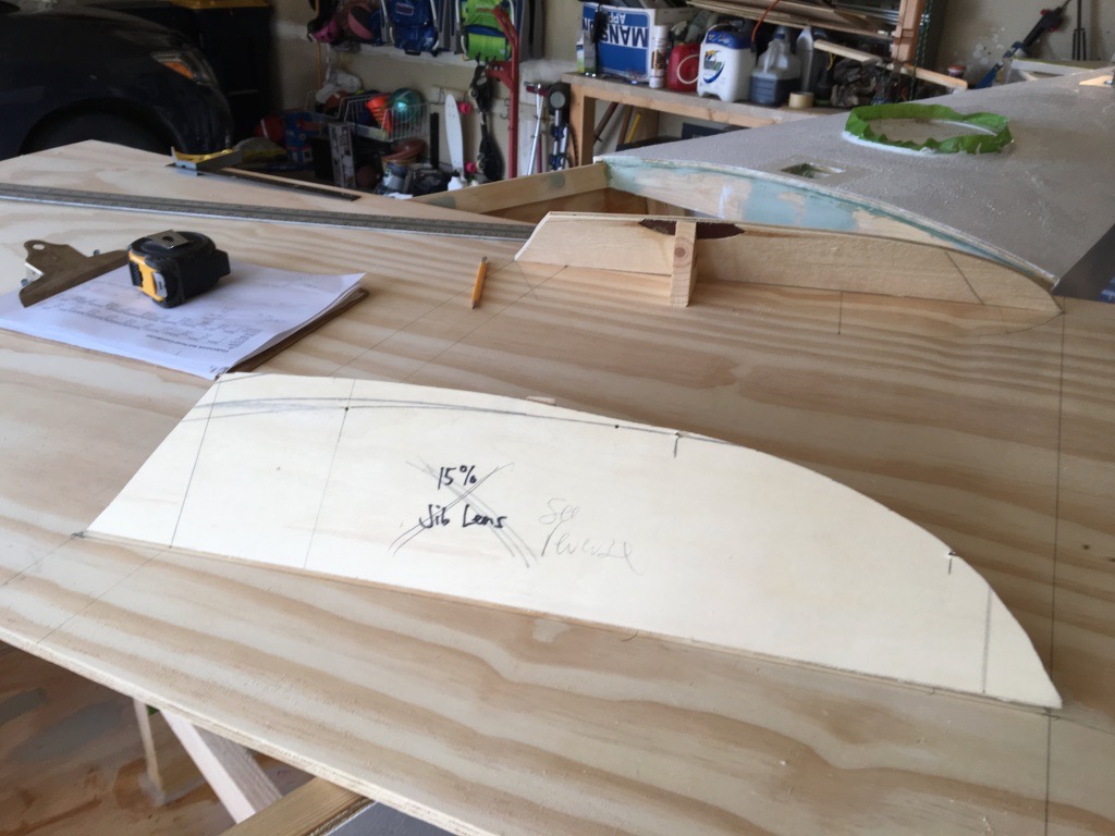
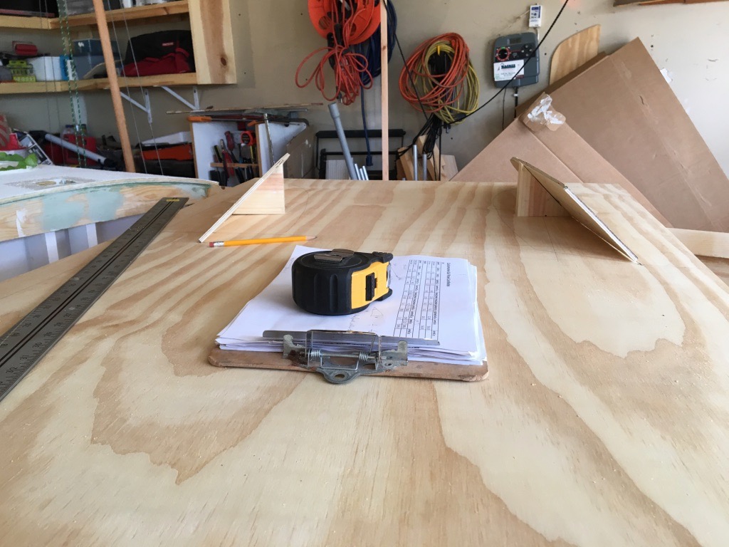
The lens templates are attached with 45 degree angle blocks. This is the jib template.
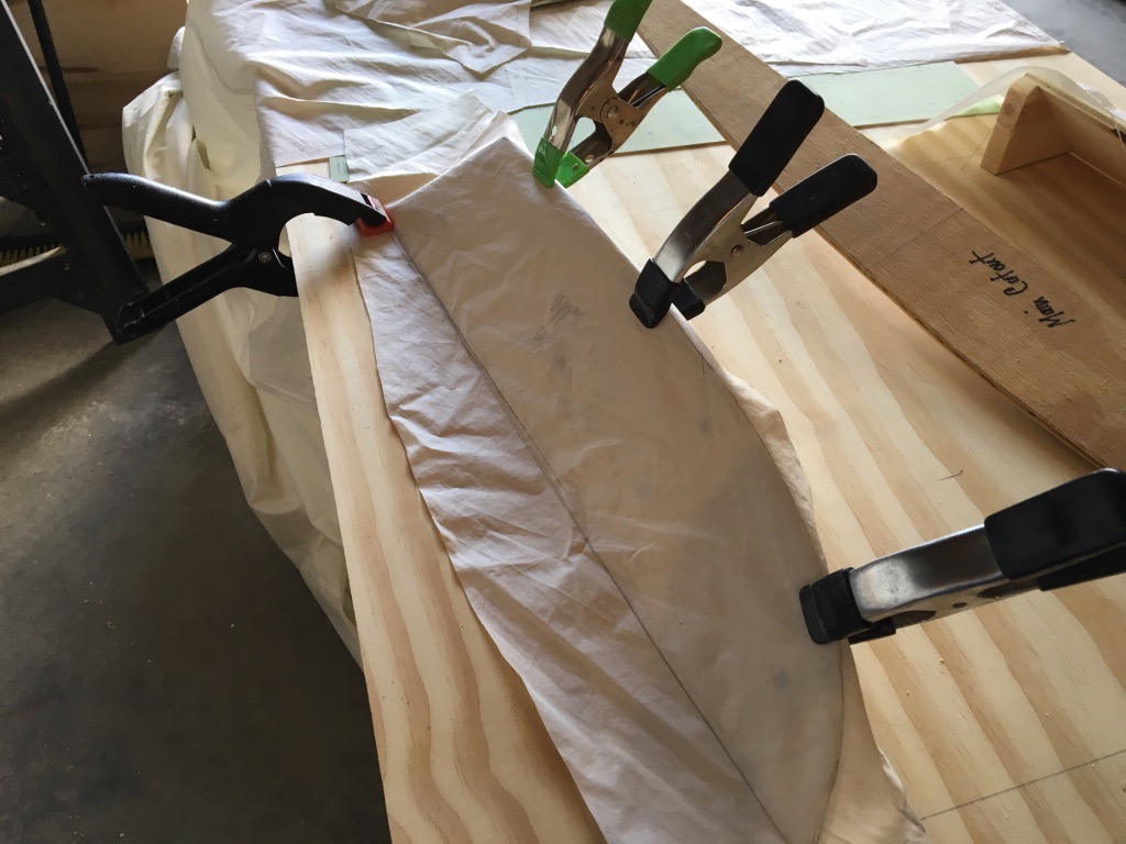
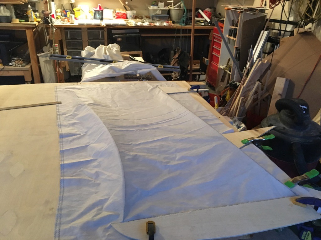
Then the fabric is stretched over the template. I use a pencil to mark the top edge of the lenses, add a seam allowance on all sides and cut out the center part of the panel.
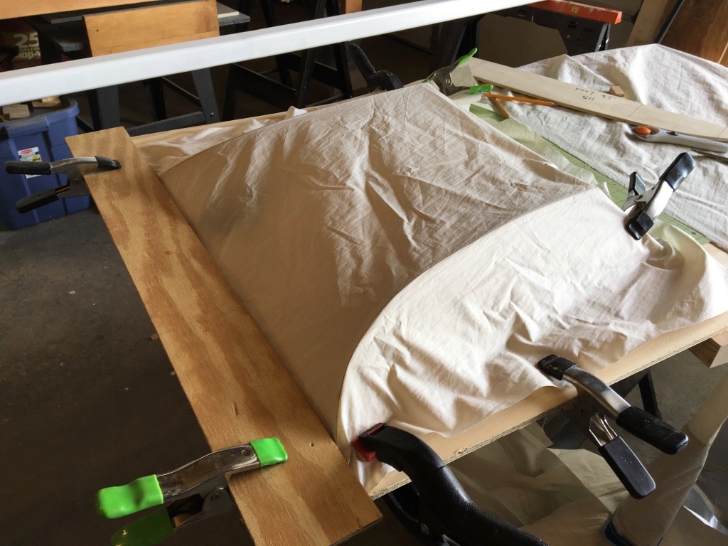
Using smaller pieces of fabric, fit them to the jib lenses and do the same thing (trace and add seam allowance).
The same process is used for the main panel template.
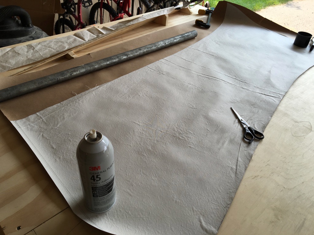
Since there are four each of the jib and main panels, I took the time to make templates by spray gluing the first set of panels to some builders paper. These can be quickly traced to cut the rest of the panels without having to fit them over the 3D template each time.
The top triangle panel did not have any templates. I just used the battens as a guide and added seam allowance. This panel is not cambered, as it is effectively the storm canvas and flat cut is fine at that point.
The “vise mast” prototype showed that left to its own devices, the sail won’t hang right. A peak-hauling parrel was added to tension the top of the yard and correct this. You can sort of accomplish this with the downhaul/batten parrels, but it requires a great deal of tension. Leaving that to the peak-hauling parrel makes using the batten parrels easier. It is one more line to adjust when reefing however. Tradeoffs…
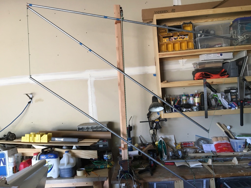
If the sail is of a manageable size, it’s handy to check it as you complete panels.
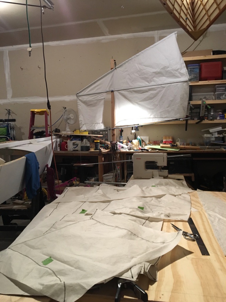
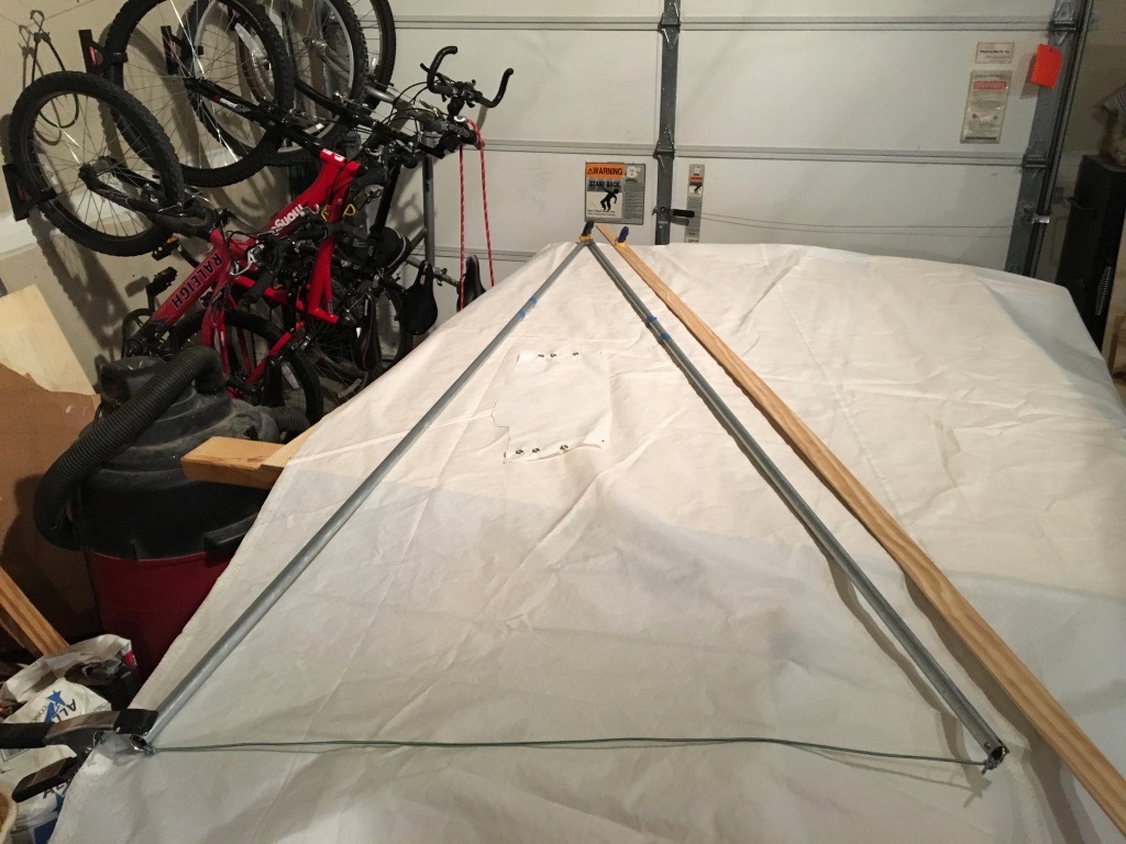
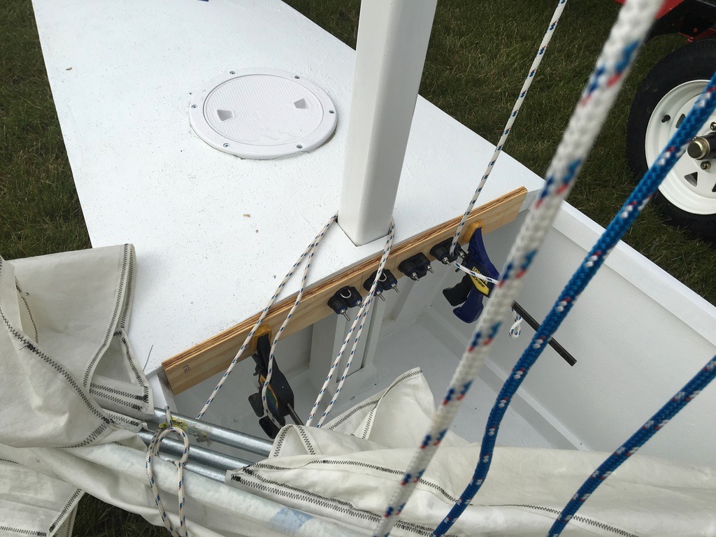
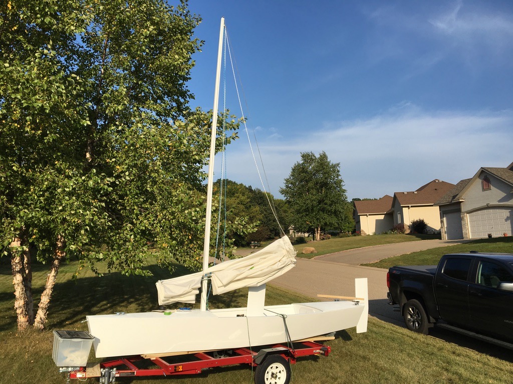
I clamped up a panel to allow me to experiment with setting up the running rig. I trailer-sailed it in the yard until I came up with a setup I thought would work.
The finished product. You can see the peak-hauling parrel going to the top of the yard.
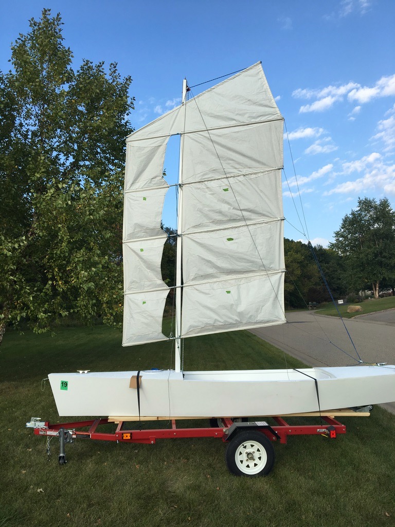
Sail fully reefed in the lazyjacks.
Unfortunately, I cannot comment on its performance on the water. While I was extremely happy with how the sail turned out, the experimental hull I put it on had some fatal stability problems and I haven’t had time to build a new test platform. TL;DR - you can’t just scale down a larger hull. That’s another story for another time.